Handy M0100
Feb 2025 - May 2025I turned a 40 year old Apple Mouse into a speech to text button for my computer.
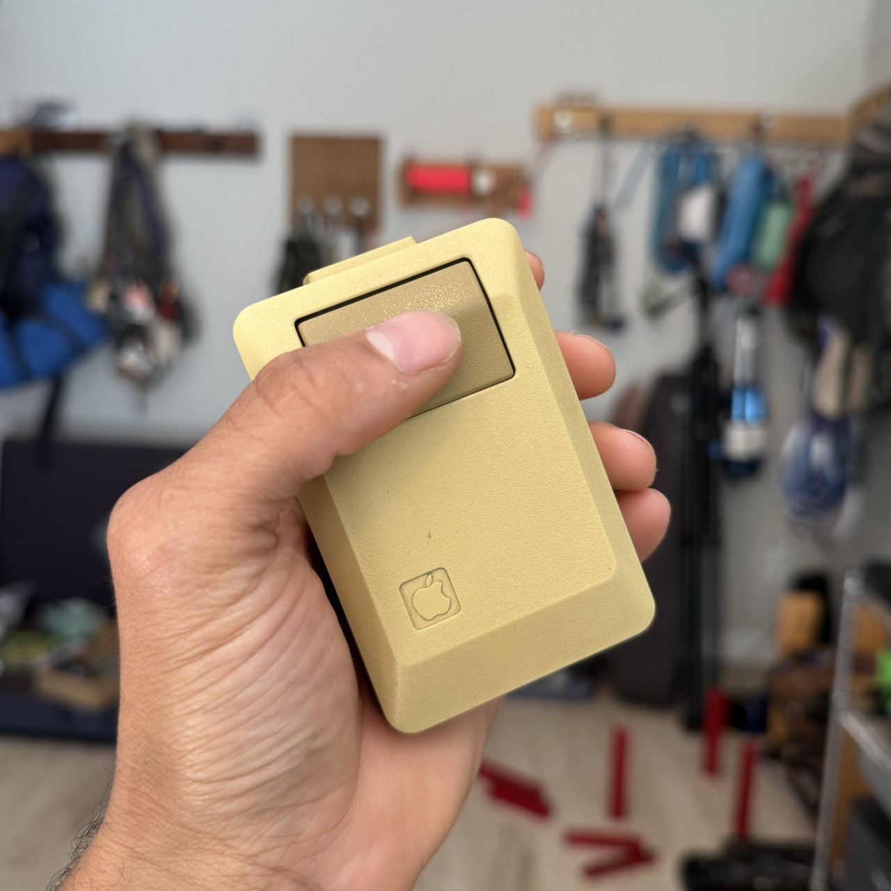
This is an Apple M0100 Mouse from 1985, originally designed for the Apple Macintosh. We're gonna turn it into a wireless input device, built for speech to text.
The Handy M0100 features:
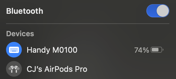
- Wireless Bluetooth connectivity
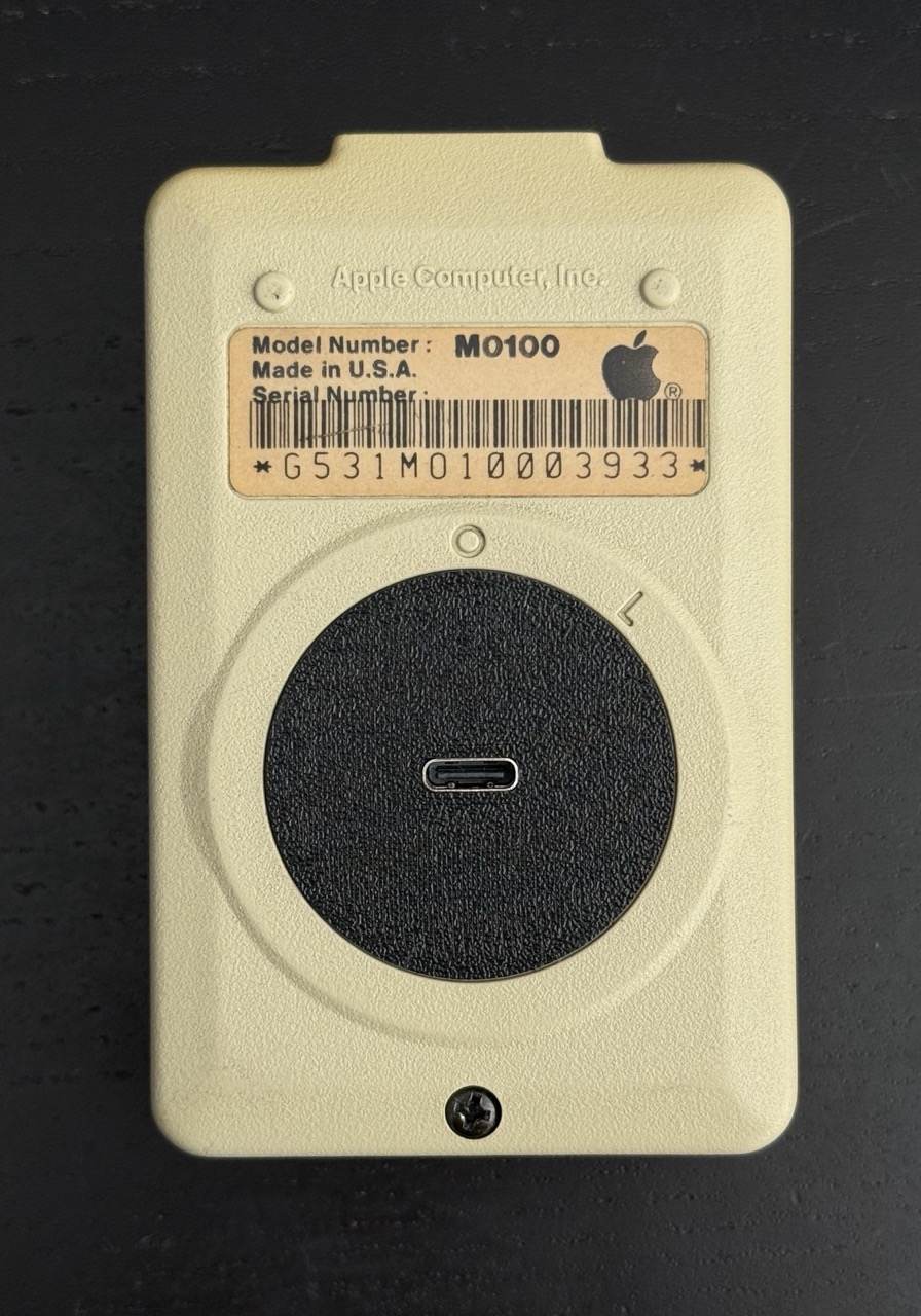
- Convenient USB-C charging via a port on the bottom
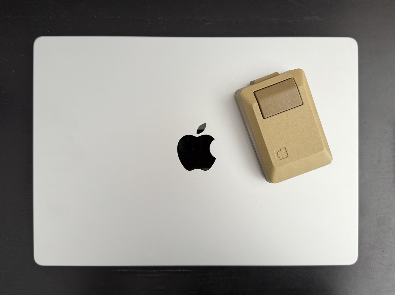
- A classic, iconic design. An ideal complement to your Macbook.
Wanna learn more? Well strap in, I got a lot of details below. If you prefer video, check out the short or full length YouTube Video
Backstory
I went to the SoCal Vintage Computer Fair with my friend Jordan. At the time I had a broken finger and had been working on the Footy foot pedal. I had just finished the prototype, so going into the event I brought Footy. I saw PCBway was a sponsor and I was interested in talking to someone there about the possibility of making custom PCB design for it. While I didn't end up making a custom PCB for Footy, bringing it got me thinking about foot pedals and vintage computer hardware that could be used for one.
Jordan and I walked around for a while enjoying all that the fair had to offer. I learned a bunch about all kinds of hardware I had never seen before. On the first lap around the fair I did take notice of the vintage Apple mice. I half joked with Jordan about turning one into a foot pedal, and on the second lap I was seriously considering it. Mostly for the laughs, I found one and put it on the ground to test how it might be. It was hilarious to me, and it totally worked great as a foot pedal.
I knew I had to buy at least one. Be it for a foot pedal, or just as a really unique speech to text button for my computer. Early on at the fair I bought a couple of Byte Magazines from a guy, and he happened to have a few of these mice. I asked him if he was willing to sell two of them, and he agreed, 2 for $40. Some other guy told me I was getting a good deal, but honestly I had no idea if I had. It was only later I went on eBay to check, and it seems like I did. I figured getting 2 of them was a good idea in the case I were to break one which seemed highly likely given my lacking disassembly skills.
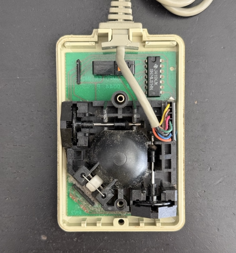
As soon as I got home, I wanted to open it up just to see what the insides looked like. When I tried opening up the first one, I ended up breaking some of the clips because I didn't go on YouTube. I just brute-forced it apart, but this was good enough to get a look at the guts.
Prototype Exploration
I had a bunch of initial thoughts as soon as I cracked it open. First I thought, maybe I could splice a USB-C connector onto the existing cable. This seemed like it could be a pain for a few reasons, but would be a no-go because I wanted to keep the original cable intact. It also wasn't clear to me how I could splice on this connector and have it look original still.
With these observations the first few constraints emerged.
- Be nondestructive to this Apple mouse. It should be able to return to service after I have modified it for what I want.
- I wanted to keep it looking as close to an original Apple Mouse as possible.
I had a few other ideas for the prototype however. First was, I could try to reuse the existing PCB and switch that's there, and just wire it to a new microcontroller. Second idea was to 3D print a new baseplate where the switch and other components would sit on top of, and I would have a lot more room to experiment with whatever I want on the inside. This seemed a lot easier than both trying to keep the PCB intact as well as somehow fitting whatever new microelectronics needed to go in it.
Initially my plan was to use USB-C, like Footy, but I wanted a removable connection, not a permanant one for whatever reason (now that I think of it, it would be rad to make a new cable that looks original and just has a USB-C connector on the end). Ultimately I tried this, but there wasn't enough space for a USB-C port on the front of the mouse. So wireless seemed like the way, but how would it charge? Oh. Of course, it will charge using USB-C on the bottom of the mouse. Just like a Magic Mouse. It all makes sense now.
With this in mind I started to get to work on the first prototype.
Building the First Prototype
Deciding on the Microcontroller
Before doing anything, I needed to find the smallest possible microcontroller since I didn't have a ton of room to work. I figured this decision may influence how things would be laid out on the baseplate so I wanted to get it done first.
It turned out to be a fairly quick task. However, I was expecting to use whatever microcontrollers were suggested by QMK, but realized that QMK has limited support for Bluetooth keyboards. So I looked around and found ZMK which looked purpose built for diy wireless keyboards/input devices. And reading through the docs it was clear I should use some microcontroller based on the Nordic nRF52840. I did need it to be as small as possible which kind of threw out the possibility of using the common microcontrollers for ZMK like the nice!nano. But I did have some experience with the Seeed Xiao series which are tiny, so I looked and they had the Xiao nRF52840, I figured this would be perfect. It was also listed in the docs as compatible with ZMK so away we went.
3D Modeling
Baseplate
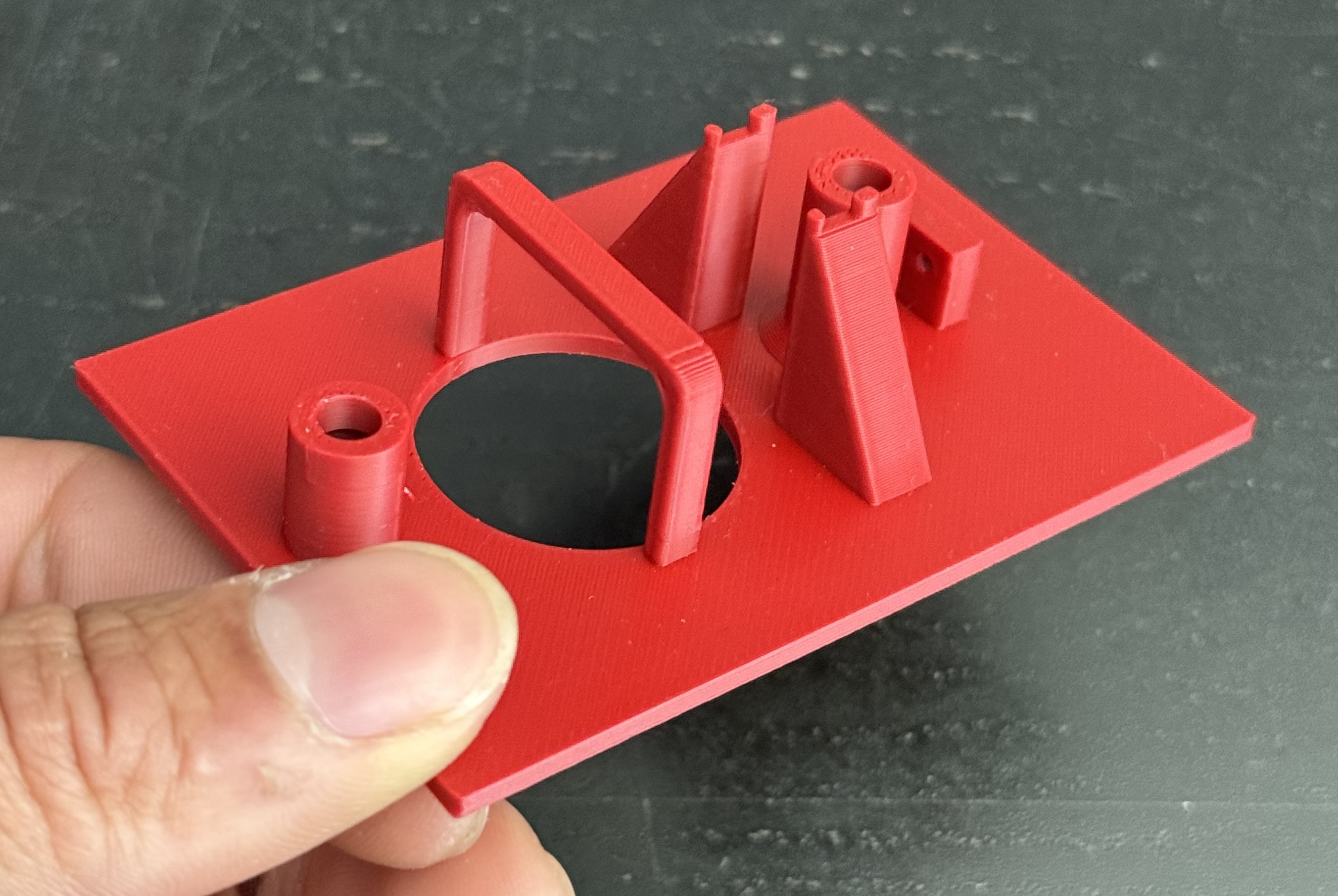
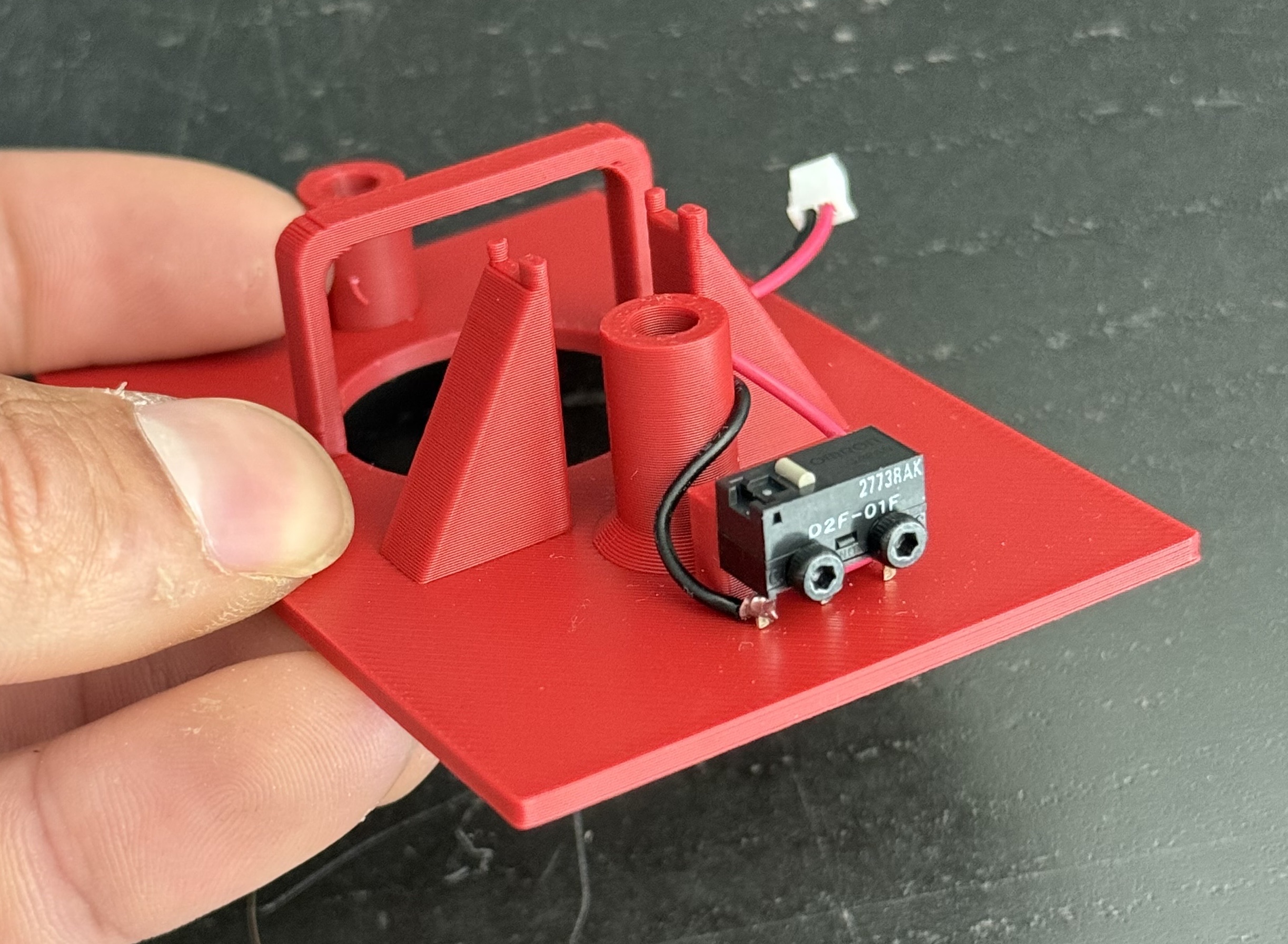
The big task was going to be modeling the baseplate to fit in the M0100. I measured the original M0100 PCB, as well as a bunch of the structures. Things like the screw holes, the trackball hole, and most importantly the structure which holds up the button. With all the dimensions I modeled the baseplate in Fusion 360.
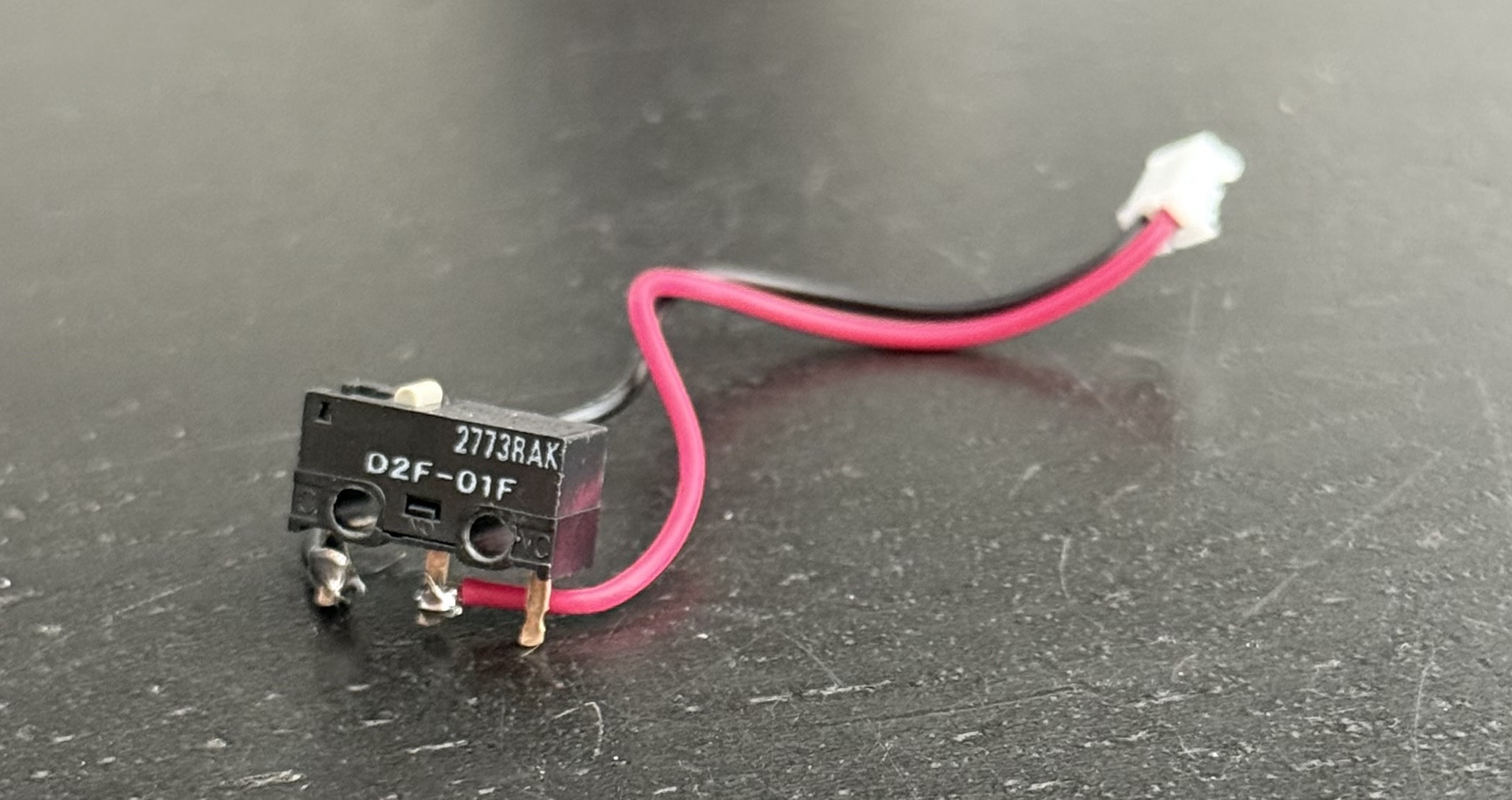
I also would need a switch to attach to the baseplate, I wanted to try and use the same switch as the original Apple Mouse, but the most available switch for the prototype was the Omron D2F-01F which is commonly used in mice today. It also ended up being a more or less perfect fit for the baseplate and just screw into it. Though it is much smaller than the original switch and definitely does not have as satisfying of a 'click'.
I will say it took me forever to create nice enough structures for the mouse to work. Specifically the towers which hold the button presser thingy. While the structures are not perfect, they are good enough for me. I probably went through about 30 iterations of the design to land where it is now.
Another feature you might notice is the 'bridge' that is over the hole where the trackball originally went. This is an additional support structure for the Xiao. Basically ensuring that when you plug in the USB-C cable to the Xiao it doesn't push it out of the USB-C charging plate. More details on that below.
USB-C Charging Plate
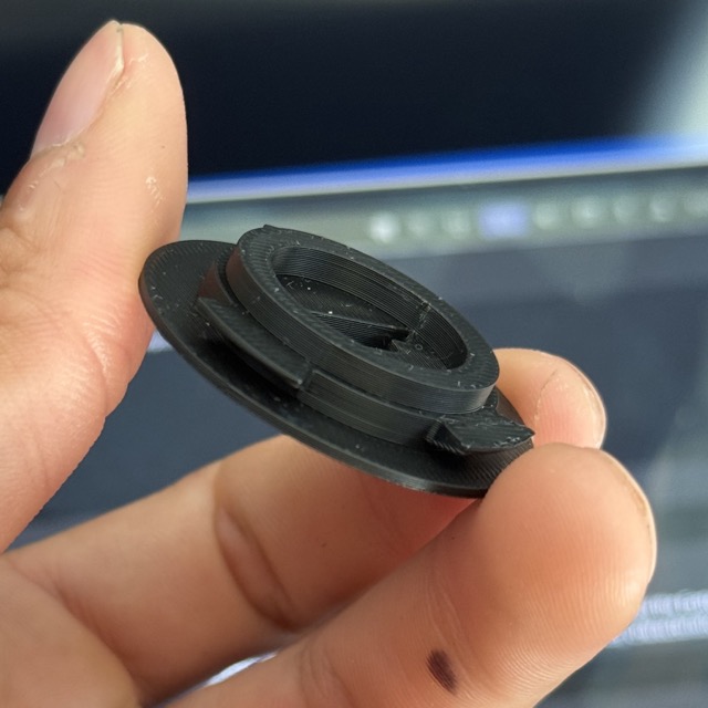
On the original mouse, there is this little twist off plate which holds the trackball in place. This was exactly the area I wanted to put the microcontroller through, which meant I needed to design a new plate so that the USB-C port for charging would be accessible. This was a pretty fun thing to model, it needed to twist and lock into place, as well as have a tight fit for the microcontroller. I measured Apple's original plate quite carefully and was quite proud that my first iteration of the design printed and worked. I did make a few tweaks to the design, but overall it's almost exactly as originally designed.
Fitted to the bottom of the mouse it looks something like this. Looks damn good if you ask me.
Assembly
Soldering
Time to solder everything to the Xiao. I typically start with the battery, and I like to make everything removable which means soldering some JST leads onto the Xiao. Usually LiPO batteries use JST-PH so I used those for the battery connector. When soldering the leads to the Xiao I use the positive pin on the battery section, and the ground on the board itself. You can also solder directly to the board (as below), but it's pretty tight and scary, especially for a soldering noob like me.
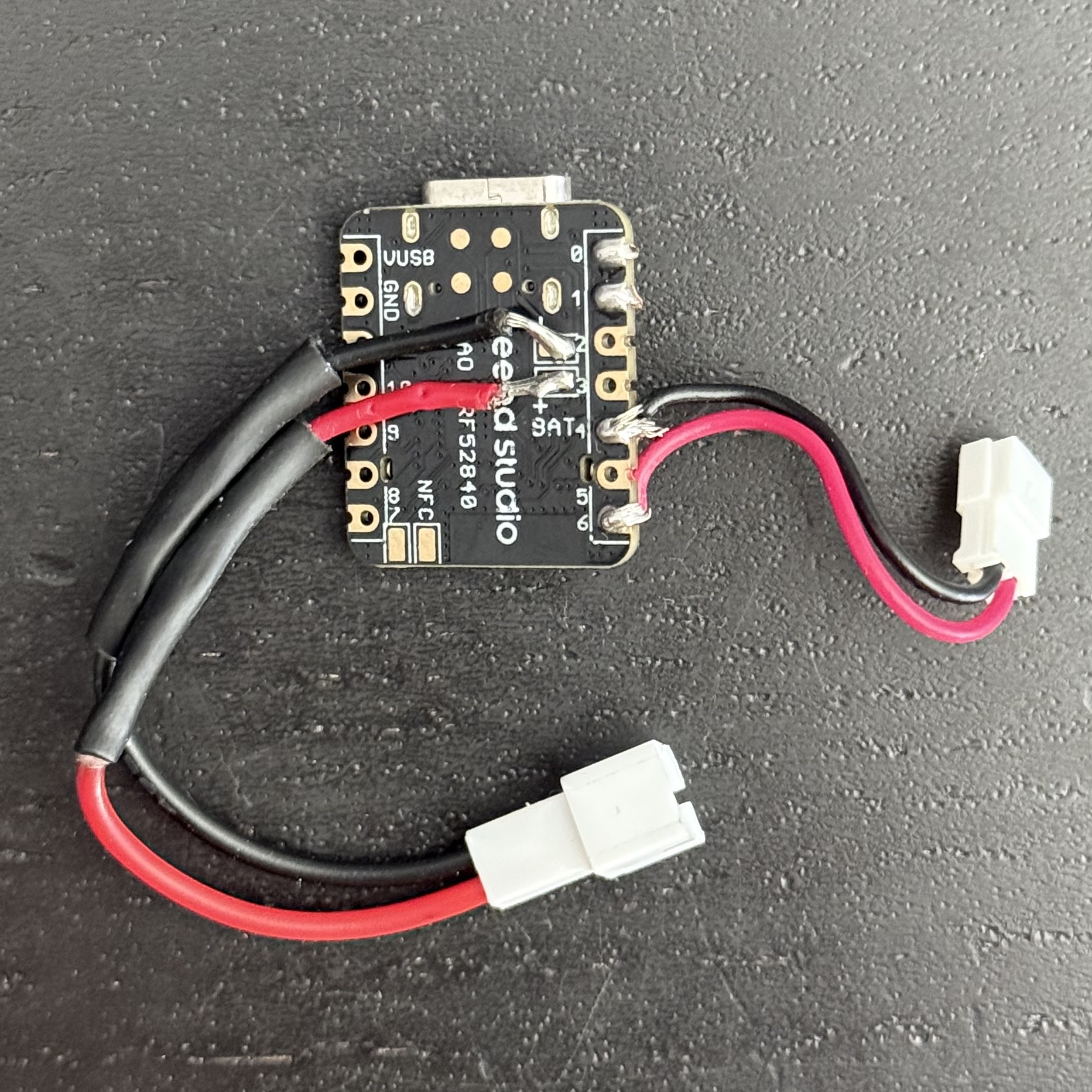
For the switch I used a JST-ZH Female connector, soldered to pins 4 and 6 on the Xiao. When the switch is contacted it should complete the circuit and trigger the appropriate keypress.
Next is soldering some leads to the switch. This is pretty simple, and I just soldered a JST-ZH male connector
directly to the feet of the switch. You will want to solder to the leg labeled C and NO. NO stands
for "Normally Open" which means that the circuit will be closed when button is pressed.
Flashing the Firmware
Now is the perfect time to flash the firmware. You can flash it and then plug everything into the Xiao then test to make sure it works before you assemble anything else. As I mentioned above I used ZMK for the firmware, and you can find my repo here. The firmware is built using GitHub Actions and can be found in the actions tab of the repo.
Flashing the firmware is relatively simple. First download the firmware.
Then plug the Xiao into your computer and double click the tiny button near the USB-C port to put it into
it's bootloader. Drag and drop the .uf2 file onto it, it should reboot, and you
can test if it works.
The default keymap is a "mod-tap"
which will hold down Right Control + Right Meta as long as the button is pressed.
This is the default key used by the Handy desktop application (coming soon! open source!). However once the firmware is flashed you can easily
change the keymap using ZMK Studio to suit
the application of your liking. Plug the mouse in via USB and it should just work.
Assembly
The assembly of the mouse is fairly straightforward once you have everything soldered together.
- Screw the switch into the baseplate using M2x10mm screws.
- Twist the USB-C Twist Lock Plate into place in the mouse.
- Put the Xiao into the USB-C Twist Lock Plate with nothing connected to it,
- Put the baseplate into the mouse, moving the wires around as necessary.
- Attach the switch JST connector
- Attach the battery JST connector and put it into a nice place.
- Screw the baseplate into the mouse with the original screw
- Put the original spring into the top hole near the switch.
- Carefully reassemble the mouse. I find that I can place the switch presser on the structures and put the mouse body on top and it generally works.
- You have a Handy M0100! Go connect it to your computer and give it a try!
Prototype Reflections
I was pretty happy with this version. Everything worked decently well, and it was so rad to use this old mouse with my modern computer. Plus the battery life was surprisingly great. I did enable deep sleep on the firmware so the mouse will disconnect after a few hours of inactivity. This means when I sit at my desk for the first time I usually just click the button and it will boot back up and connect to my computer.
One thing that kept nagging at me was the other M0100 I had laying around. It still had the original PCB and switch. It kept clicking it and it was just so damn satisfying. Something the modern Omron switch and my custom baseplate just would not be able to match. So I decided to try reusing the original PCB and switch.
Using the Orignal PCB
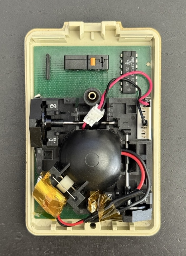
After I figured out all of the stuff from the other version, using the PCB became a pretty simple task. More or less it was just a matter of stuffing everything into the original spaces and connecting to the original switch.
What made all this possible was the tiny size of the Xiao. When removing the trackball from the mouse, I could slot the Xiao in that space perfectly. So the main problem was to both connect to the original switch and place the battery somewhere.
Connecting to the Switch
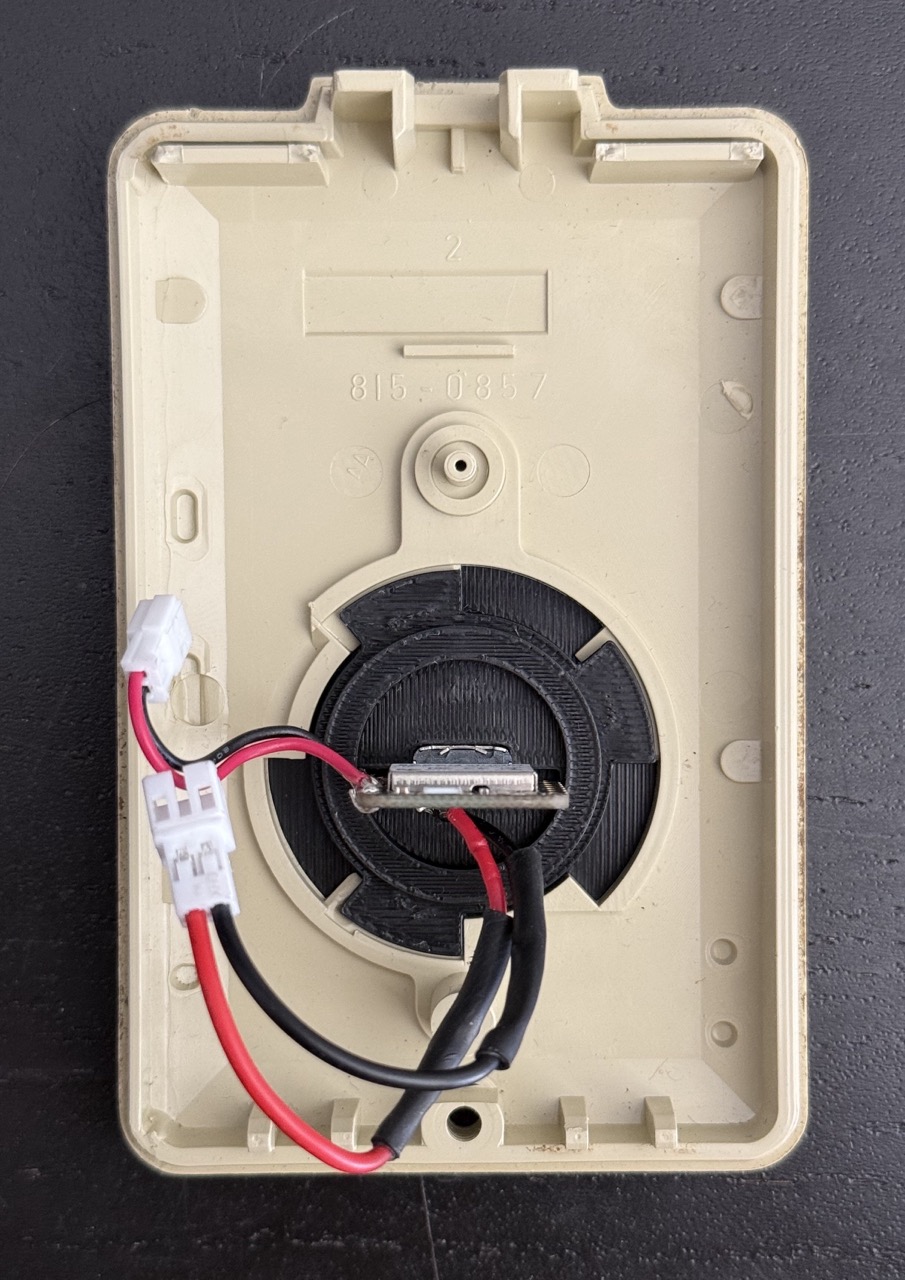
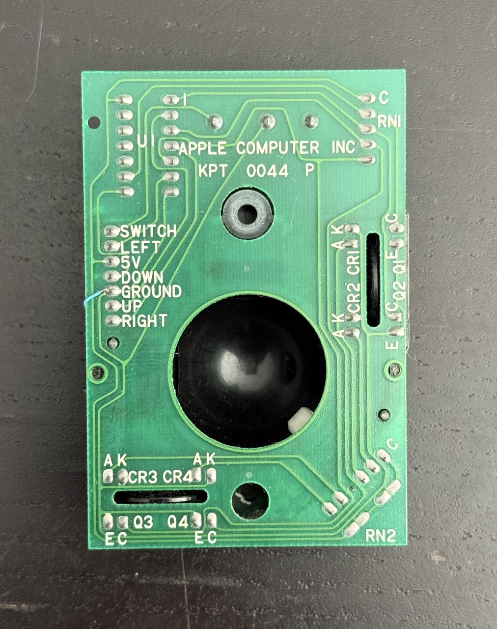
To connect to the switch I took a look at the PCB and traced some of the wires. On the top side
we have a molex connector where the original cable was connected. Unplugging that we have a bunch
of pins which go to the switch and trackball. Turning the PCB over, on the bottom we see
labels for SWITCH and GROUND which map to the pins on top. So we will connect these
to pins 4 and 6 on the microcontroller.
I made a custom little cable with Dupont female connectors on one end to connect to the PCB, and on the other end a JST-ZH male connector. This connector would connect to the JST Female connector on the microcontroller. The JST-ZH is tiny and can be sqeezed through the holes around the trackball structure which made things easier to work with.
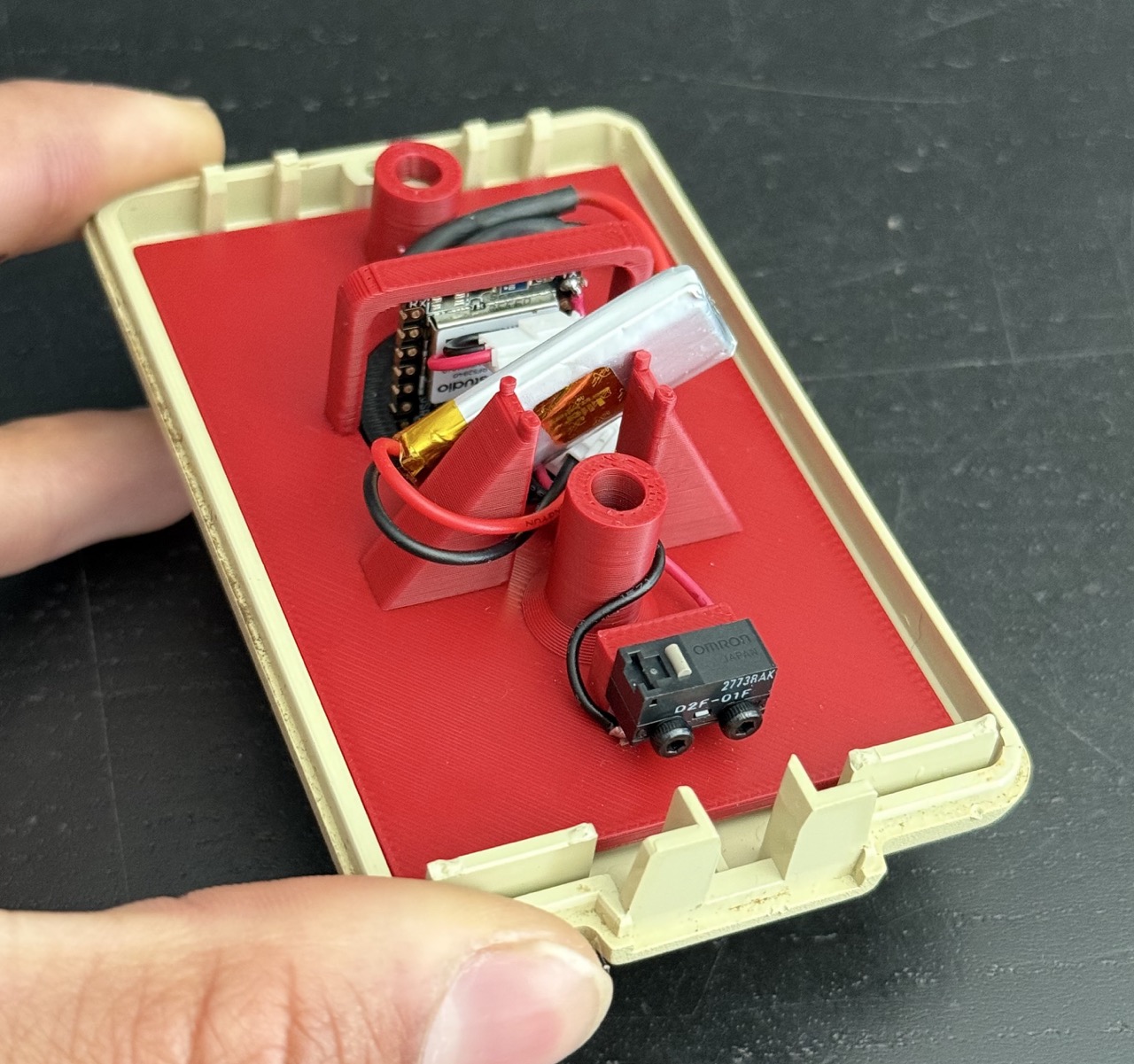
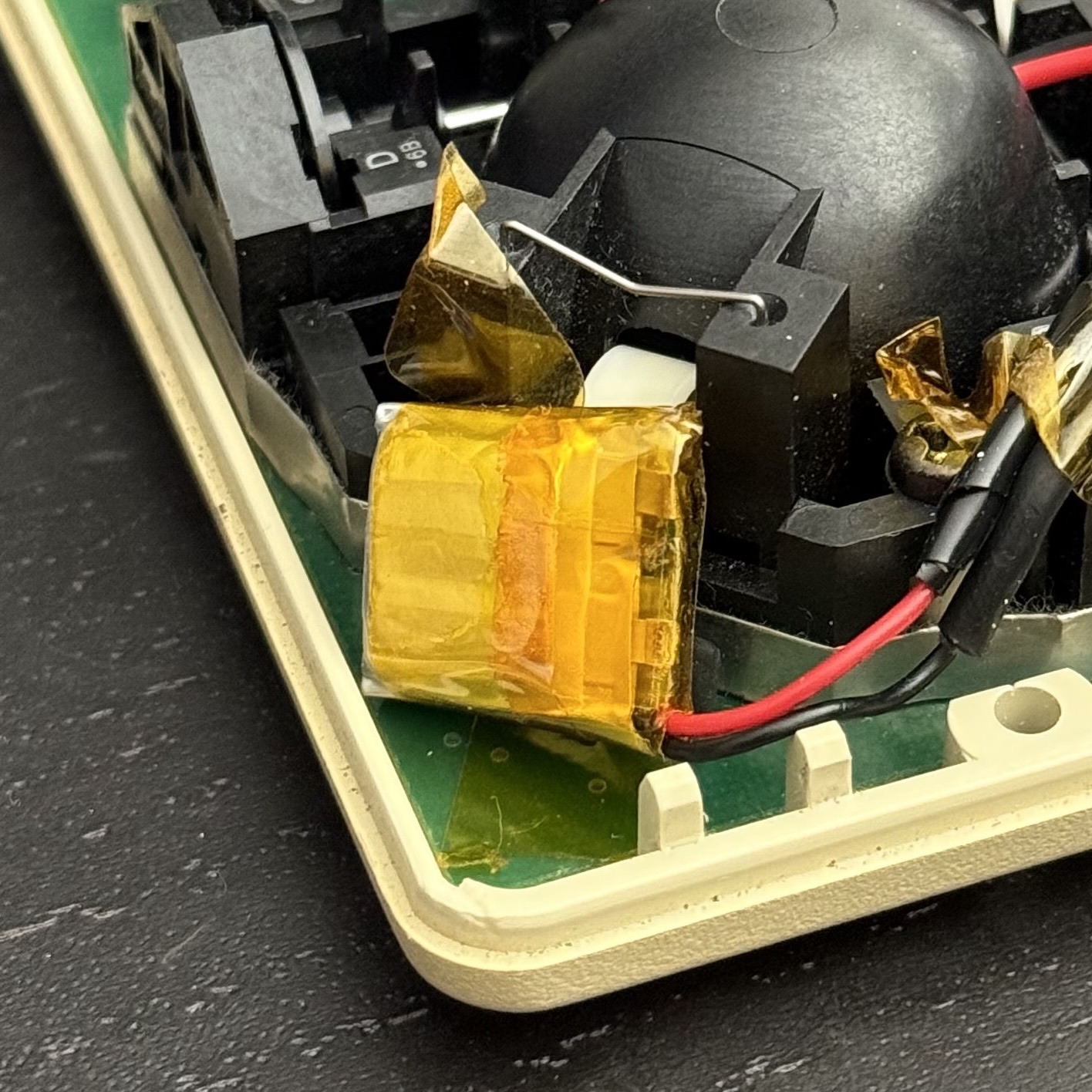
Placing the Battery
The only thing left is a place for the battery. I chose an 80mAh battery since they are quite tiny, and probably could fit many places. Sure enough on the corner of the mouse there's a space it fits quite nicely. Some of my leads were a long or awkward so I just taped them down as necessary.
Final Assembly
Since everything is small and the fit is tight, it takes a while to fiddle around and assemble the thing. But once assembled, it looks pretty great I think. Putting the mouse back together generally goes pretty smooth for me. The biggest trick I learned for this version is to assemble the mouse upside down. It's a little less fiddly to do it this way.
Feelings
I think there's something very aesthetically beautiful about the M0100. It speaks to a simpler time, and I kind of hope that computers can be simpler again, in many ways. I feel like the world has just made them so complex because the world is so complex. But sometimes you just need something simple. Things that don't need to serve many purposes for millions of people, but things that serve the perfect purpose for a few. I think that's in many ways what this project represents for me. It's certainly not something for everyone and that's a wondeful thing. It suits me, and not gonna lie, having a 40 year old mouse and turning it into something still useful today is fucking rad as shit.
Not to mention it's actually genuinely useful. While I love my foot pedal, it's not portable. I can't travel very easily with it, but I can totally throw this 1980s mouse in my backpack and carry it with me anywhere. Talking to my computer has become a staple in my day to day life, and most of this post was sketched using my voice. Typing is still useful for syntactics, but it's nice to have my literal voice shine through I think.
Wanna Build One??
Hopefully I've done a good enough job of talking through things here that it's easy enough to do. Here are the resources you may need.
If you have any questions email me: cj@cjpais.com
3D Models
Hardware
For the 3D printed baseplate version you need:
- Xiao nRF52840
- Omron D2F-01F
- 2x - M2x10mm screws
- JST connectors (optional)
- LiPO Battery - The 180mAH I used
- Misc Dupont Cables
For the PCB version you need:
- Xiao nRF52840
- JST connectors (ZH)
- LiPO Battery - The 80mAH I used
- Misc Dupont Cables
Firmware
Future?
This project has been a blast and I really love using a old Apple mouse with my modern computer. A fun juxtaposition. There's something that feels right about it. I've never really tinkered with older hardware before and I feel like this was maybe the easiest introduction I could have into that world.
One thing I would really love to do is make an actual PCB with a better switch soldered onto it. It would be really great to make some better structures to hold the button itself as well.